This will assist in replacing v groove roller in Pro Edge II to IV machines. Actual time will depend on condition of miter box.
- Position the miter around 160 degrees and turn off power to the machine. Lock out / Tag out.
- Disconnect all the air lines going to your spindle. There are four air lines going to the air cylinders. Mark each line for location before removing.
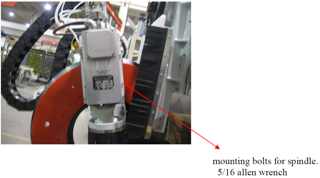
- Remove the four bolts that mount the spindle to the miter box. Lay the spindle on the table.

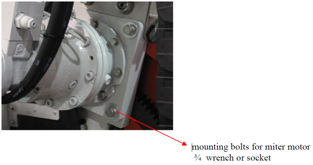
- Remove the four bolts that mount the hydraulic miter motor to the miter box. You can leave all the lines hooked up to the motor. Lay the motor with the lines connected on the table.
Note: Once you remove the miter motor, the miter box will be free to fall down the C arm. Take precautions to make sure this doesn’t drop.

- Remove the outer set screws that tighten the inner roller. Item #1 on the drawing. Once you remove the outer set screw, there will be a second one below that. Loosen the second set screw about two turns.
- Remove the 4 bolts that hold the two halves of the miter box together. Refer Item #2.
- Remove the nut that holds the inner roller to the plate. Refer item #3. The plate then can be taken off of the C arm and the remaining rollers can be removed.
- Put the new outer rollers in the plate and tighten completely. Leave the inner roller loose so you can mount the plate on the C arm.
- Once you have the plate on the C arm, snug up the nut for the inner roller.
- Assemble the two halves of the miter box. Then snug up the set screws that push on the inner roller shaft (These set screws should still be in the two plates. Refer item #1.
- Now completely tighten the nut for the inner roller. Refer item #3. Tighten up the set screws that push on the inner roller. Make sure to tighten both set screws equally. The set screws should be tightened until the box is tight around the C arm. You may need to check it at 0, 90, and 180 degrees depending on the wear of the C arm. Put the two outer set screws back in and cover with silicone.
- Assemble remaining parts in reverse order of removal.
- Lower miter to 0 degrees and cycle power to zero encoder.

 Adding the right machinery provides real results. Understand the impact at these shops.